Artbook Sketching in Maya
This style captures the immediacy and energy of a quick sketch. It features loose, expressive lines that dance across the page, suggesting form and movement without focusing on precise detail. You can almost hear the scratch of the drawing tool against the surface.
1. Scene Setup

So create two RenderMan Distant light sources. The naming of these lights and their position does not matter, and in this picture they are indicative only. We are interested in rotation only. So rotate them from the left and right of the sphere as seen in the image.
All the presets in this pack will require a UV map for each object to function properly. So make sure the sphere and plane both have a UV set applied.
I’ve started with a default scene scale. First created a sphere with default values and raised it 1 unit above ground.
Added a plane, this time though I’ve increased the width to 25 and the length to 25. Do not scale the default plane to 25 units. Instead modify the polyPlane node width and height. This is required for the initial value for the UV coverage.
This presets require two lights in the scene. Each light will be responsible for it’s hatching shadow that is different for each light.
2. Render Controls
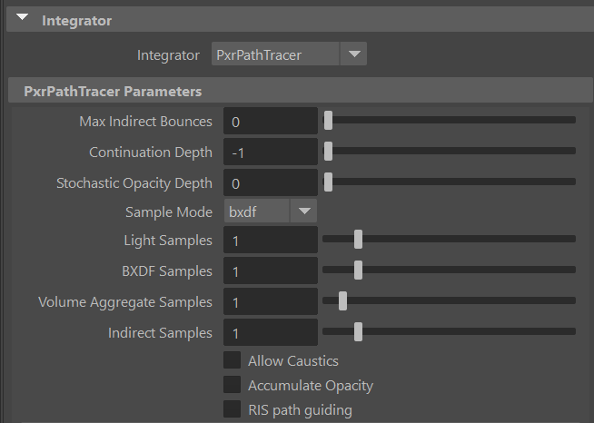
1- Make sure the renderer is set to RenderMan in the render settings dialogue and Integrator is set to PathTracing. Then set the Maximum Indirect Bounces to 0.
Leave everything else on this tab to default.
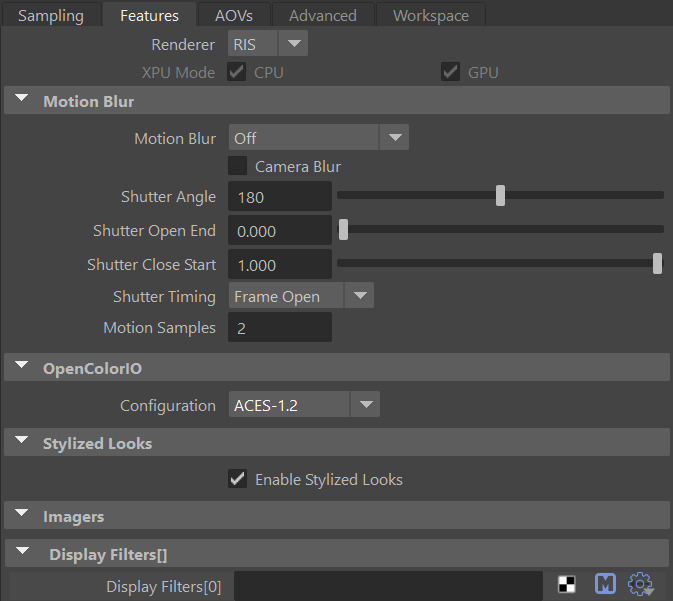
2- Switch to the Features tab and make sure the configuration is set to ACES 1.2 and enable Stylized Looks
3. Applying The Preset
We’ll be adding the presets twice. One for the sphere and one for the plane.
Select the sphere and right click on the Artbook Sketch presets and select import and assign to selected.
You’ll be asked if you want to add the preset’s displayFilters to the scene? Choose YES.
Another dialogue box will appear. This time asking if you want to add the preset’s displayChannels to the scene? Choose YES.
The displayFilters are the actual Stylized Looks layer stack. without it the scene will render with default materials just like any other RenderMan scene.
The displayChannels are the AOVs and/or LPEs that are required in the scene. Stylized Looks operates off of AOVs and they are crucial to its function.
There are default Stylized looks AOVs. Those one are added behind the scene and are not displayed in the AOV list (You can add them individually if you want by choosing them from the list)
This presets require additional custom AOVs. We’ll see how to tackle those in step number 7.
Next select the Plane and again import the presets. This time however, Choose NO for both the displayFilters and the displayChannels dialogue boxes (The displayChannels dialogue might not show up for you and that is ok). Choosing YES will load the displayFilters again and displayChannels in addition to the previous ones. So make sure you select NO.
Once the presets is loaded and the material is added to both objects in your scene, open the render settings again. Check the features tab and make sure the list of displayFilters are loading as the image below and there are no duplicates.
Click the AOV tab and make sure the 4 main directDiffuse and directSpecular are loaded as well.
Note, the content of these AOVs are empty due to a bug in current version. We’ll show ways to fill them up or recreate them from scratch in step 4 below.
4. Light Setup
I want to do a test render and make sure everything is working properly so we can start fine tuning in the next steps.
However, if we try to run an IPR right now or render to it we will not have any of the hatching filters working. This is because the additional AOVs are empty. We need to recreate them. I can give you the LPEs for each channel to copy and paste or we can recreate them from scratch.
Thankfully in Maya it is easier to recreate and this would be a good opportunity to learn about light group LPEs, so we’ll do that instead of copy and paste :)
So open the AOV tab in the render settings if you’ve closed and select all 4 AOVs and press the right most
”minus” button.

Next, select the first light (I choose the one on the right pointing towards the left). Open the attribute editor. On the PxrDistantLightShape node scroll to the Advanced tab and expand it. Where it says Light Group type MAIN in the empty field.
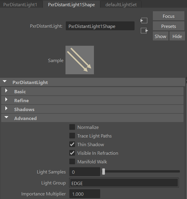
Now select the other light and this time name the Light Group EDGE.
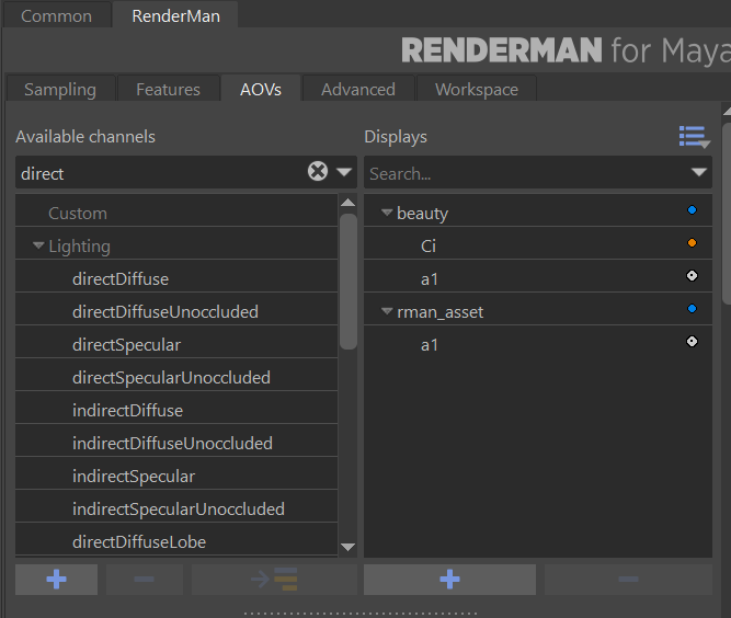
We’re close to launch out first render but we need to recreate the AOVs we deleted earlier. Open the render settings and switch to the AOV tab.
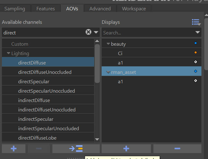
Start typing the word direct in the search box above the available channels in the left pane.
Select directDiffuse from the left pane.
Select rman_asst from the right pane.
Click the arrow that indicate that the channel will be added from the left to the right.
Once added select the new AOV that was added. it will be named directDiffuse. In its properties below you’ll see an expression in the channel source, and below the channel source there is an empty LPE Light Group.
Select the drop down menu from the LPE Light Group and choose MAIN from the list
The AOV channel will be renamed to directDiffuse_MAIN
This adds/recreates the deleted directDiffuse_MAIN that was loaded when we added the preset. This time though the LPE expression is loaded and the light source is populated. We need to do this 3 more times. Do the same steps as above to create the following AOVs
Create a directSpecular AOV and pick the LPE Light Group MAIN, so the resulting channel name will be directSpecular_MAIN.
Create a directDiffuse AOV and pick the LPE Light Group EDGE, so the resulting channel name will be directSpecular_EDGE.
Create a directSpecular AOV and pick the LPE Light Group EDGE, so the resulting channel name will be directSpecular_EDGE.
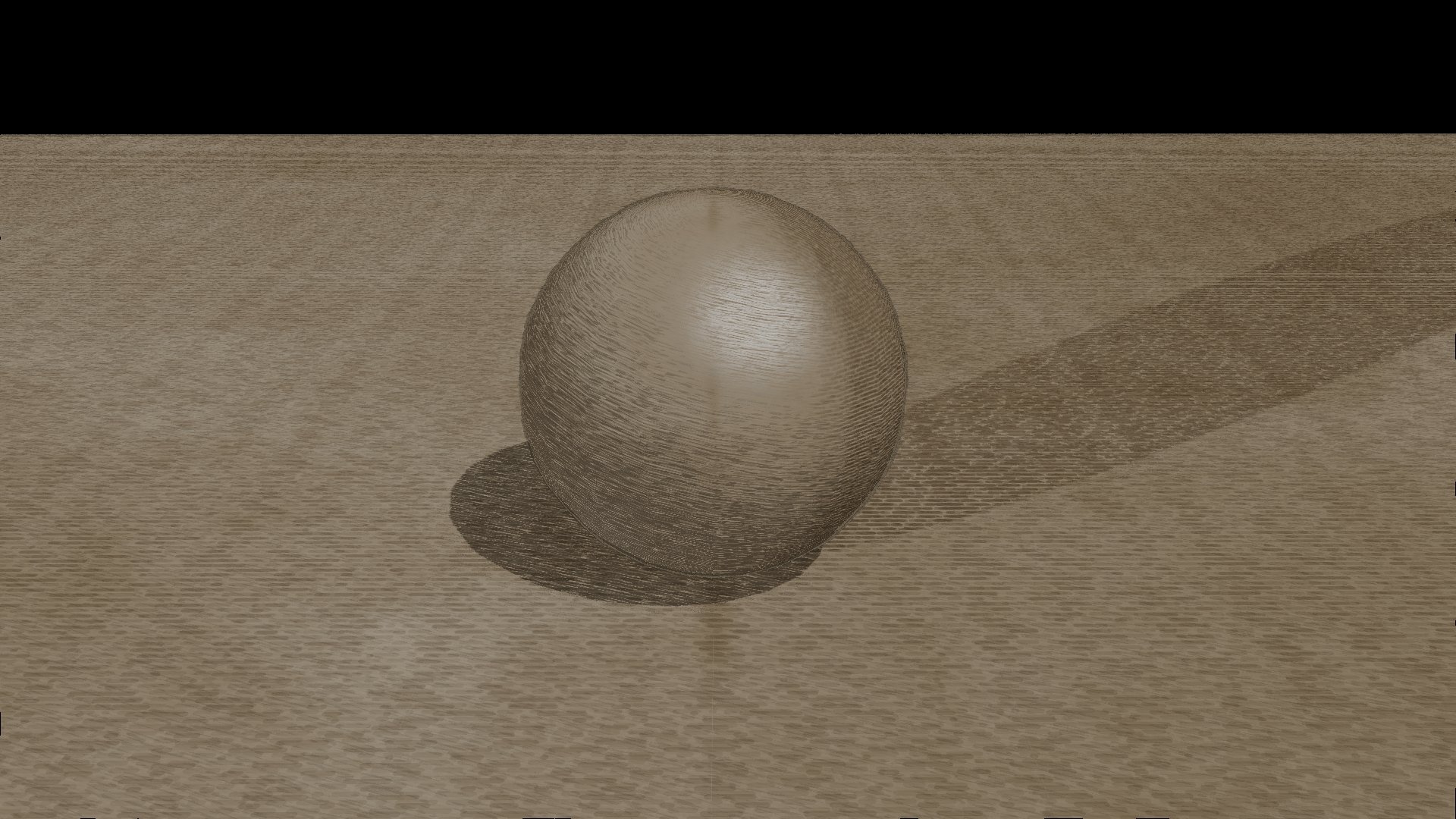
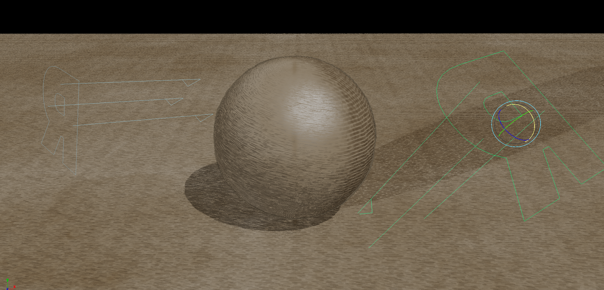
5. Initial Render
Nice, this doesn’t look bad at all, but it needs improvements. This is largely due to the scene scale. Let’s break down the areas of improvements and how to tackle them.
The hatching on the left side is from the MAIN light on the right. it appearing in the shadow areas only. The frequency (or scale of the hatching) is too small on the sphere. It is ok on the plane. So we need to fix that. This will be fixed at the material level for each surface.
The hatching on the right side that looks like dashed line is coming from the left EDGE light. This hatching is bigger than intended and will be scaled down on the sphere. This will be fixed at the displayFilter level. We might need to tweak the value for the plane afterword’s and that will be done at the material level.
The specular is setup the same way as the hatching from the MAIN light. So by fixing the initial hatching it will fix the specular as well.
Let’s jump to the next section where we tweak the hatching frequency form the MAIN light
We are ready for our first render of the Presets. Hit render and you should have the following result.
6. Material Tweaking
There are a few elements here:
The PxrStylizedControl make the surface properties available for the Stylized Looks displayFilters.
The controls in PxrStylizedControl can act as an override for the controls found in the displayFilter. This allows finer control on object by object basis. It also acts as a mask for some parameters, for instance if you didn’t want an object to have an outline this is where you would find the control to do so.
PxrManifold2D node plugged into the PxrStylizedControl. This node will allow PxrStylizedHatching to map the hatching on an actual UV of an object. The first hatching from the MAIN light is projected on the surface UV. So the PxrManifold2D is where we will be tweaking the frequency scale.
There are 2x PxrFractal nodes that are plugged into the Distort U and V respectively. These fractal nodes allows to add noise to the line work and even move inside, outside or partial in an object, if we choose to. Its existence in the shading network doesn’t meant it will unless we activate it from the main displayFilters.
A PxrWorley node that is plugged into the line thickness. As you’ve guessed it this will allow us to vary the thickness of our line, if we choose to. Its existence in the shading network doesn’t meant it will unless we activate it from the main displayFilters.
The PxrStylizedControl is a non-destructive node. Meaning it will allow any object with a an existing material to render with Stylized Looks and turned into an illustration. So if you import an existing object with any shading network (even the most realistic one) and plug a PxrStylizedControl to the main surface Utility Pattern then your object will be seen by the stylized tools displayFilters and it can read the existing information off of the surface.
Time to tweak those hatches. Start an IPR session while we do those edits.
Select the PxrManifold2D for the Sphere and reduce the Frequency S and T to 10.
Select the PxrManifold2D for the Plane and increase the Frequency S and T to 40.
The hatching is the correct size (you can pick any value, correct is relative here). However the hatching on the plane is way too much and I want to reduce that.
I can either lighten the Plane diffuse channel, but it will create a visible difference in hues and values of the image.
I can add another light to the scene that doesn’t belong to any LPE light group and have it lighten the whole scene or just the Plane.
I can rotate the MAIN light to point slightly down to have a more direct impact on the floor.
I’ll choose No. 3 and the result is shown below:
For Maya I have created scripts that either plug a PxrManifold2D into an existing PxrStylizedControl or allows me to call out the attribute of PxrStylizedControl or PxrManifold2D from an object as I tweak those controls constantly while developing the looks. You can download these scripts from this github repo.
Load the materials for the sphere in Hypershade or the Node Editor.
The shading network is controlled from the PxrStylizedControl node. This node plugs into the Utility Pattern of the PxrSurface node. It can plugin in a LAMA surface as well.
7. PxrStylizedHatching
The controls we want are found under the Project tab. In there you’ll see that we are using 8 values for the frequency and that the projection mode we are using is Triplanar. With Triplanar the hatching doesn’t use the UVs of the object, or any projection method applied to the object, instead it creates triplanar projection from NPRPtriplanar & NPRNtriplanar AOVs (written out from PxrStylizedControl). If you were rendering to IT you could expand the list of AOVs and see those AOVs directly.
With an 8 values mode we are saying to the hatching that we want to start with a value of 0.9 (direct lit area) and transition to 0.97 (shadow most area).
These values are designed. I hate to use the word trial and error because that suggests there is a correct value. There isn’t a correct value. There is just how small or large do you want the hatching to be for your particular scene scale at the time of creation and tweaking. Since we are loading a preset that was made from a different scene scale the values are bound to be different and will need tweaking.
The way I work is I try to find the initial starting value. For that I always work with a mode set to 1 value. Because I want to get the scale of the texture correctly. Once found I can find the gradual scale.
Switch the mode to 1 value. The value will change to 0.200
Why did it change to that value? it is the default value for any new scene. However, if you’ve set this to something like 0.750 and then switch to 8 values and saved the scene, the next time you open the scene and switch back it will be 0.75.
The 8 values mode was 0.9. The current 0.2 value for the 1 value is way to big. We want smaller values. We can start by doubling the 0.9 to be 1.8 and increment or decrement slowly from there.
The starting value of 1.8 looks good and matches the size of the hatching from the MAIN light on the sphere. Slightly bigger, but we can remedy that by figuring out the smallest value in the shadow area. Once we get smallest value right, we can switch to 8 values and work out the increments for ourselves. Or you can leave it as a single value. This is purely a taste thing. For me I’ve settled for a maximum value of 2.0. So my transition will go from 1.8 to 2.0.
We’re almost done. The dashed hatching on the Plane is way to small and causing artifacts and streaks. These will flicker in animation and will require a large sample count to filter them out and they will still flicker. Better to fix them now. As you recal from earlier. The PxrStylizedControl is where we can override controls for individual objects. It happens that we can set an initial scaling value for the Triplanar params for each object in PxrStylizedControl.
Select the Plane and bring up the PxrStylizedControl attributes. Expand the Hatching Projection and you’ll see three scaling values for the Triplanar. I started by halfing the original value and worked down from there. 0.375 looked good to me
To edit the displayFilter more conveniently, assign a single tab in the node editor for these controls. First, filter out only DAG objects in the outliner. Next, search for PxrStylized in the search bar to reveal all displayFilter and pxrStylizedControls. Choose the filters exclusively. Then, open a node editor and establish a dedicated tab. Click the plug icon to incorporate these nodes into the tab. You have the option to rename the tab, and the changes will be saved with the scene. This method streamlines node selection, particularly beneficial when working on a laptop to avoid cluttering the workspace with multiple open panes.
The displayFilters are named appropriatly by their function and layer (think photoshop) The first layer in the list is the bottom layer and gets applied first. The rest of the filters goes on top. We call this setup Daisy chaining. Look for the PxrStylizedHatching_Dashed and click on the arrow to display it’s properties
Time to fix the hatching on the right side. For that we’ll need to open the render settings and switch to the Features Tab. Keep the IPR window open to view our changes as we make them.
Make sure the attribute editor is open for this step as well. Have both the render settings and attribute editor open side by side.
Congratulations!
These steps might have seams like a lot. And they are if you just started using Stylized Looks. As you gain more proficiency with Stylized Looks you’ll be able to set this up quiet quickly. And most of the presets aren’t that involved and will load out of the box. Tweaking the hatching values will always be required, so this long tour is necessary so you know how to get the most out of these presets.
So swap that sphere with your favorite model, and make it is has UVs and hit render.
Preset perfection? Show your appreciation!

Back